Shop Temperature
It should be at least 40 degrees (F) in your shop while the Cricket is in use. Running any air hammer below 40 degrees will likely result in ice formation in the valves and damage them.
If your shop is not heated, you might consider using a heat lamp to keep air circuit components from being damage by ice.
Air Quality
It’s important that air hammers receive consistent air pressure with clean, moisture free, oiled air.
Synthetic oils can damage air valve O-rings. Use non-detergent (10W) or mineral oil in your compressor and line lubricator.
Filtering air requirements vary by device. Most air valves require air filtration to 40 microns. Please refer to the documentation you receive with your valves to determine specific minimum filtering requirements.
If you neglect this requirement, it’s likely your pneumatic valves will fail prematurely.
If the hammer is a significant distance from the compressor, or there is ferrous metal in the air line (Iron pipes or fittings), it is recommended the hammer have its own air cleaner, water eliminator, regulator and oil mister close to the hammer.
Long air lines can result in loss of pressure over distance. In addition, ferrous metals will rust… and that rust will move inside the line and damage the pneumatic valves.
The amount of air pressure drop over distance is affected by pressure, run length and the inside diameter of the pipe or hose carrying the air, so a specific distance limitations cannot be specified here.
You will need to control or measure pressure near the hammer to determine if there is an issue.
Long air line runs may need to be half, three quarters or even an inch in inside diameter to avoid significant pressure drop.
Short air lines from the compressor or taps off the shop air line for the Circuit should be at least 3/8th inside diameter
Larger ID is better… and will be required when larger cylinders are used.
Preparation for Forging…
The operator should
- Ensure the regulator is set to an appropriate pressure.
The recommended pressure for general forging is 80 PSI.
The Cricket may be run with the air line pressure regulator set from 60 to 110 PSI to support unique forging circumstances.
Air pressure controls the force the Ram can hit its target. The higher the pressure, the greater the force available the operator.
- Ensure the air line oil mister has oil in it.
Mineral based (non-synthetic) oil should be used.
- Ensure the treadle and its linkage is operating properly.
The linkage from the treadle opens a butterfly valve and the Air Gate. It must open the butterfly valve slightly before opening the Air Gate.
- Close the Venting Valve (if open).
The Venting Valve is used to release pressurized air from the cylinder during shutdown. It must be closed during operation.
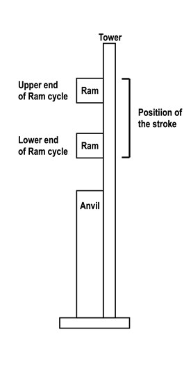
- Set the Position of the Stroke (If desired)
The Position of the Stroke should be set to support the current forging requirements.
It is set by moving the Stroke Adjustment Assembly (under the table) up or down.
Moving the assembly up moves the stroke up. Alternately, moving the assembly down will lower the stroke.
Moving the Stroke Adjustment Assembly to its lowest position will put the Cricket in Single-Hit and Clamp mode.
Please note that moving the Position of the Stroke does not change the length of the stroke.
If it moves side to side, tighten the Gibs as per instructions in Maintenance.
- Brush all scale off the table.
The Table should be clean at the start of a forging session.
This should also be done occasionally during the forging session before scale interferes with the forging process.
- Ensure the Tower is properly greased.
Follow the procedure in the Maintenance section
Normal Forging…. Although the Cricket may be considered unconventional visually and by construction, it is operated in a conventional manner.
Start Up… The Cricket is “Turned On” by slowly opening a hand valve (referred to as “Butterfly Valve 1”) at the front end of the Air Circuit. This allows pressurized air to enter the air circuit and “Makes the Hammer Ready” for the operator to start forging.
The Ram will not start cycling when Butterfly Valve 1 is opened. Cycling is initiated when the operator presses down on the treadle.
The operator, to gain access to the maximum capability of the Cricket, opens Butterfly Valve 1 all the way.
Forging… As soon as pressurized air enters the air circuit, the Ram will rise to its upper-most position and stay there, ready for forging.
There is a discussion in the Technical Description section that explains why the Ram moves to its upper-most position and stays there.
After the operator places an object on the lower die, the treadle is pressed down to initiate cycling the ram.
Depending upon the Position of the Stroke, the treadle may be pressed gingerly to administer light blows for light forging or planishing, or pressed down firmly to deliver medium to heavy blows.
As the operator backs off the treadle (lets it up), the cycling will slow down and lighten up, with the ram returning to its upper-most position when the treadle is fully released.
With light treadle movement, the ram will cycle with short strokes (not necessarily resulting in the dies meeting). Longer strokes occur as the treadle is pressed down further.
The Cricket’s stroke can be controlled to such a degree that the operator can literally just “kiss” the target by controlling the length of the stroke with the treadle.
The further down the treadle is pressed, the longer the stroke becomes, reaching toward its target (and conversely, rises higher before the ram reverses direction to start the downstroke).
 These cycling characteristics are common with all air hammers.
Advanced Features…
The Position of the Stroke is defined as the range of motion the Ram traverses during Ram cycles.
The operator can literally change the Position of the Stroke.
The stroke may be moved down to accommodate forging smaller objects with less force, or moved up to allow forging larger materials more effectively or to use tooling (such as a punch, slick, hack or spring loaded swages).
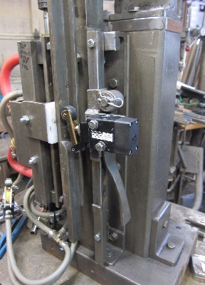 The photo on the right shows the Stroke Adjustment Assembly (under the table).
The Position of the Stroke has a direct correlation to the position of the Stroke Adjustment Assembly.
The Position of the Stroke may be moved by pulling out the lever, then sliding the assembly up or down the tower, then releasing the lever to lock in the position.
The Cricket can be put into a Single-Hit mode.
The Single-Hit feature is enabled by moving the Stroke Adjustment Assembly to its lowest-possible setting.
When the operator presses the treadle down, a single blow is delivered. The ram does not cycle.
There are many instances where a single-hit capability would be advantages. For example, when the operator is using tooling, such as a punch, or chisel…. the tool usually needs to be reset in position before subsequent blows are delivered.
While in Single-Hit mode, the force behind the blow is controlled by how aggressively the operator presses the treadle.
If the operator presses the treadle down quickly, the ram will deliver a forceful blow.
If the operator presses down lightly on the treadle, the ram delivers a light blow.
When the operator releases the treadle, the ram will move to its upper-most position, waiting for the operator to initiate the next single-hit.
If the operator does not fully release the treadle, the ram will stay down.
To return to normal forging, the Stroke Adjustment Assembly is moved back up to a position that resumes cycling.
While the Cricket is in the Single-Hit mode, the ram can be used to clamp an object between the dies. On the original Cricket, the force will be about 300 pounds at the recommended operating pressure of 80 PSI.
If you are using a larger cylinder, or more operating pressure, the force will be greater.
To clamp, the operator
- Places the object to be clamped on the lower die.
- Presses the treadle down slowly, until the Treadle is in its lowest position.
As long as the operator holds the treadle down, the object will be clamped.
To release the clamp, the operator slowly releases the treadle to its upper-most position.
The Cricket is then ready for the next object to be clamped…. or a Single-Hit action.
- Restricting the Cycling Speed… The operator may limit the maximum cycling speed of the hammer. This is done by (only) partially opening Butterfly Valve 1.
This limits the volume of air that can enter the system, which reduces the maximum number of cycles per minute the ram can deliver.
This will be advantages for some forging situations, such as working in Single-Hit Mode, using tooling, forging small stock, or when someone new is learning to use the hammer.
Shutdown… When the operator is finished forging
This prevents pressurized air from entering the Air Circuit, effectively “Turning Off“ the Cricket.
The Ram will remain at its highest position.
- Open the Venting Valve slowly.
Pressurized air that is trapped in the cylinder by the Check Valve is released through the Venting Valve.
The Ram will move down until the dies are touching.
The Venting Valve should be closed after the ram has descended so the air circuit is ready for operation the next time Butterfly Valve 1 is opened.
Maintenance
FRL (Air Line Filter-Regulator-Lubricator Units)
Maintenance will vary by design. Follow the manufacturers recommendations.
Oil Line Oil
Use only non-synthetic oil in the line oiler.
Commercial air tool oil may have additives that will damage pneumatic valves.
Plain mineral oil is best.
Cleaning Valve Internals….
If you feel the need to dis-assemble the air valves… clean only with mineral oil. Do not use commercial cleaners or WD-40. They will damage your seals.
Coat lightly with Vaseline and re-assemble.
Gib Adjustment
Try to shake the ram. It it moves side to side
- Loosen all the Gib Adjustor nuts
- Do the following for each Gib Adjustor.
- With a wrench on a Gib Adjustor nut, turn in the screw till tight, then back off one quarter turn.
- Hold the screw position with a screwdriver, then tighten the nut snug.
- Shake the Ram Assembly again… If it moves, repeat the adjustment procedure.
Greasing the Ram Assembly
Visually check the tower for grease. If it’s dry, inject a little grease through the zerks in the center of each side of the guidance system.
Do not inject excessive grease. There should be just a trace of grease on the tower.
If there is excessive grease on the tower, wipe it off.
Moly grease should be used lightly.
Notes
Excessive Moisture.
If you have excessive moisture issues, a simple moisture removal unit may not be sufficient.
Consider
Adding a commercial dryer in the air line.
Adding a Gulp Tank near your hammer to capture moisture before it enters your air hammer.
Adding a “coiled” 100 foot hose in the air line prior to a gulp tank. Moisture will condensate in this hose and can be drained from the gulp tank.
Next Section Previous